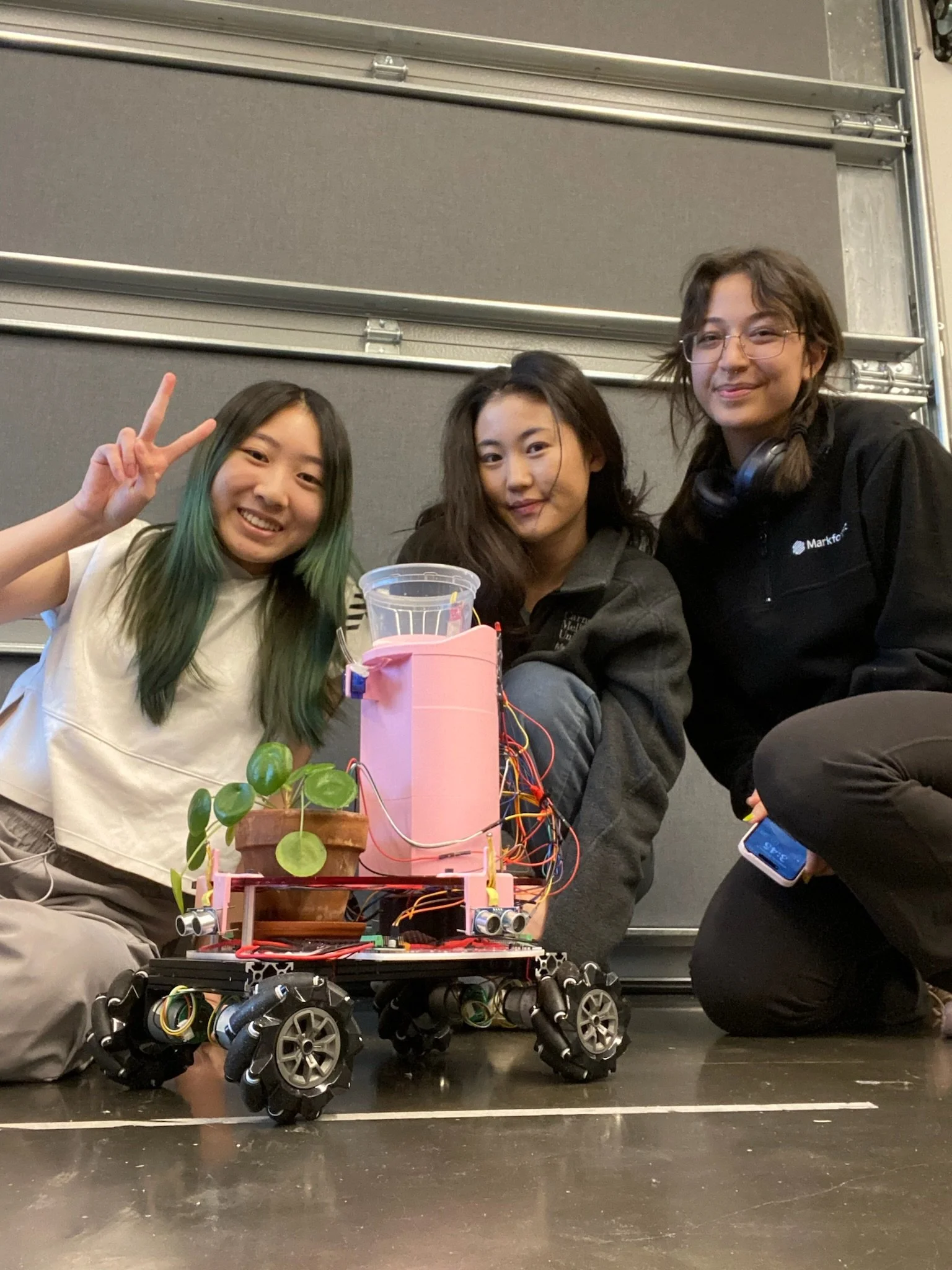
sunflower robot
COURSE :
24-354 - Mechatronics Applications
TIMELINE :
October - December 2023
BUDGET:
$500
TEAM MATES:
Janika Oh + Iris Park
Sunflower is an autonomous plant care robot that allows even the least attentive plant parents to have thriving plants - no green thumb required! Sunflower holds a small potted plant, and relocates it throughout the day to stay in the sun, as well as monitors moisture levels and waters the plant when necessary.
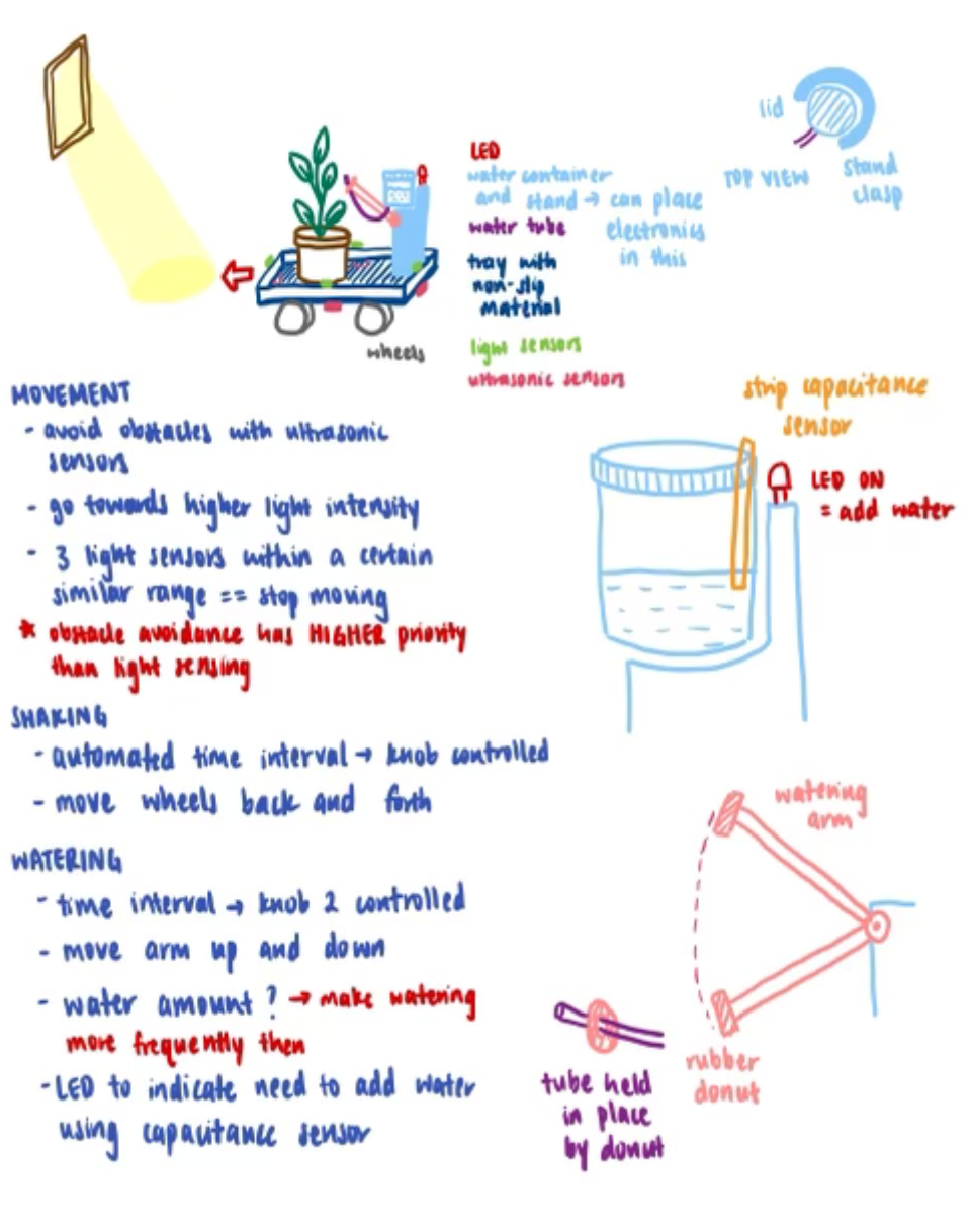
IDEATION
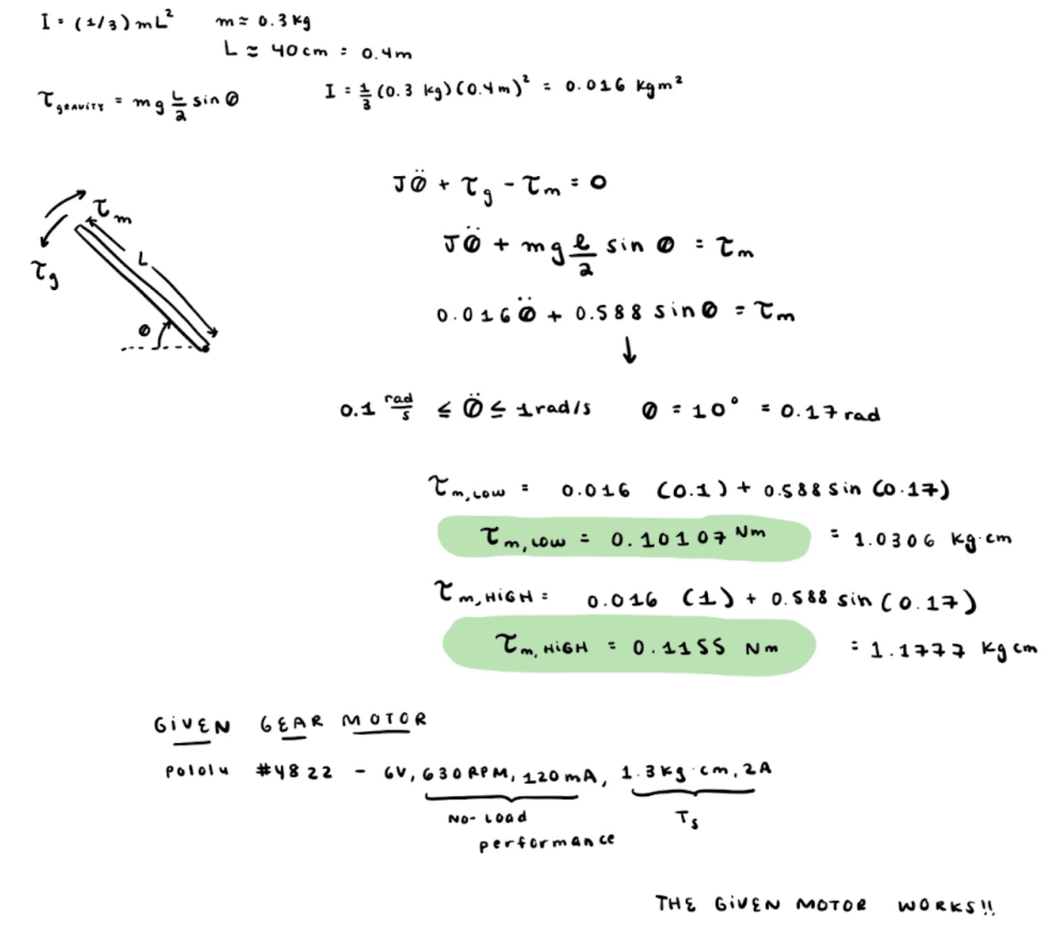
We sat down as a group to discuss the robot features needed to accomplish our technical requirements, with our budget and short timeline kept in mind. We settled on a design we all agreed with, and split into our subdivisions to do some quick hand-calculations to spec out what parts we would need to order. For this project, I led the chassis and watering tower design, and oversaw the electromechanical integration across all subdivisions when creating the full assembly’s CAD model.
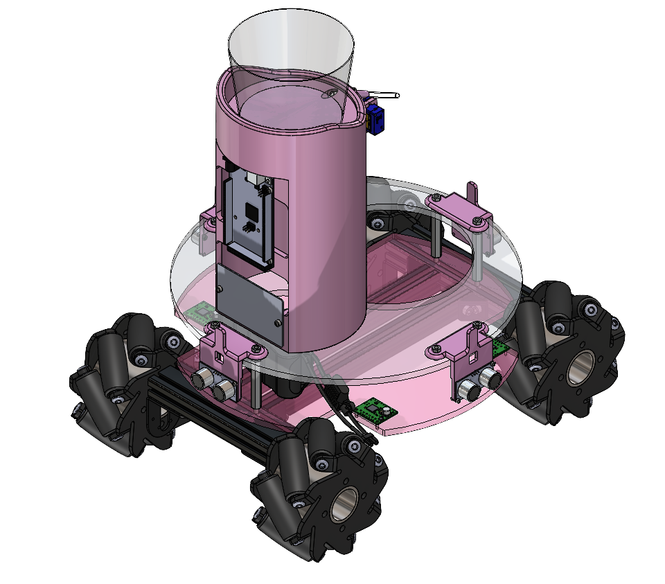
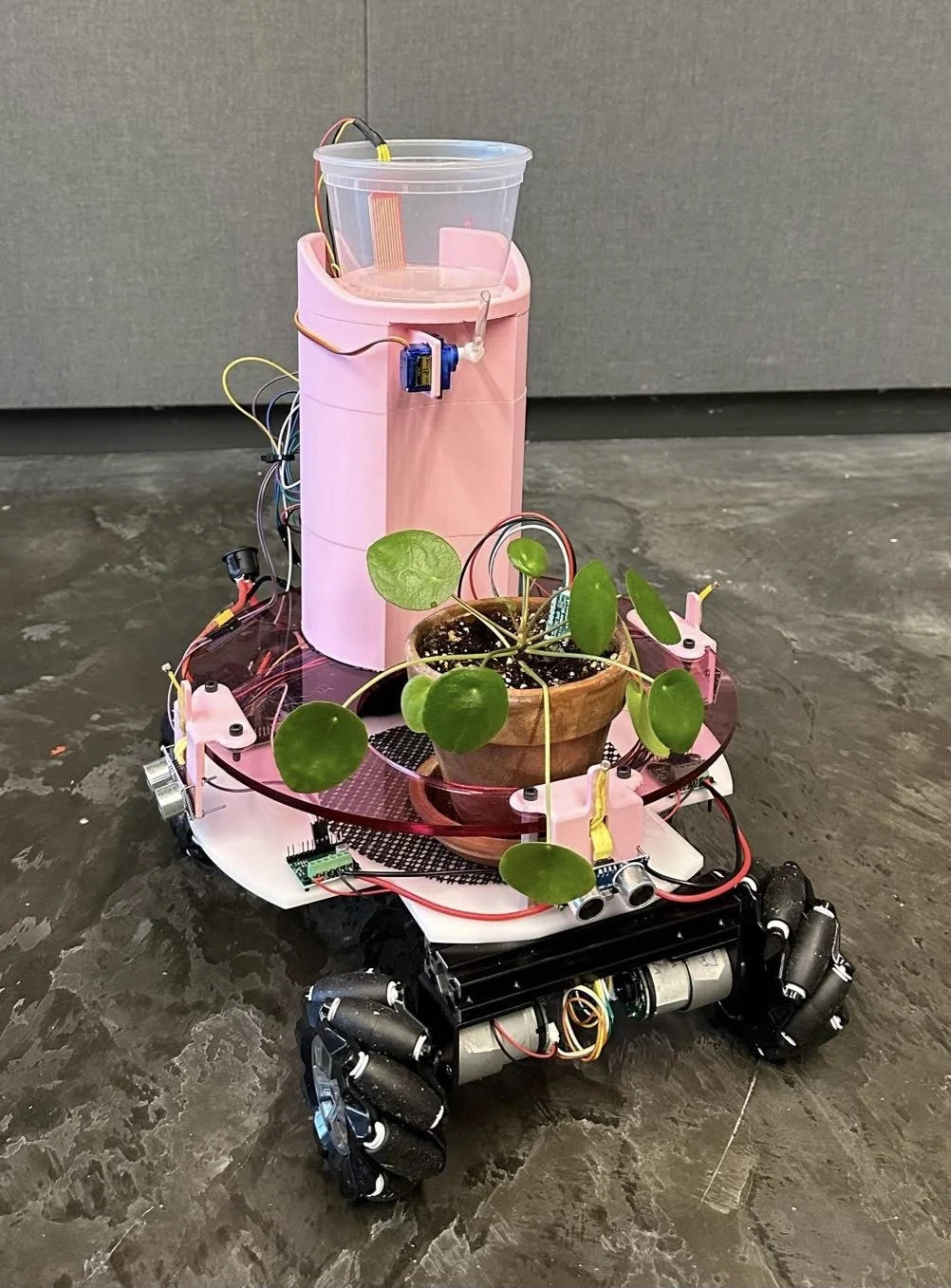
Sunflower consists of a chassis, which holds the plant pot and is responsible for moving the plant into the light and avoiding obstacles, as well as a water tower on top of the chassis, which the electronics are mounted onto and waters the plant when the soil moisture level is low.
CHASSIS DESIGN
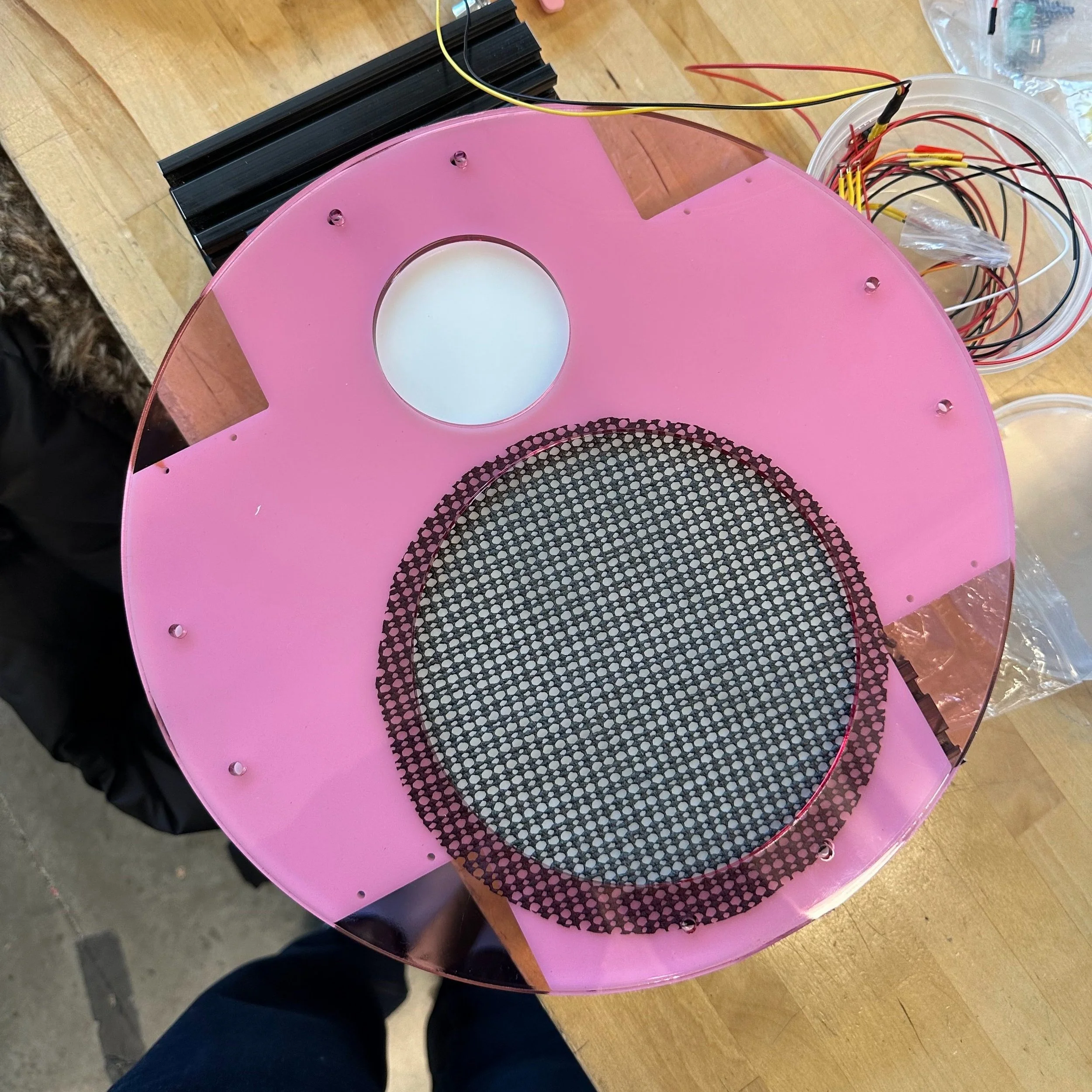
The foundation of the chassis consists of an aluminum frame with mecanum wheels mounted on for omnidirectional drive, to ensure that the robot is fully capable of navigating around obstacles with ease and easily travels to bright areas in the room. The acrylic chassis is held together with standoffs and has holes laser cut for easy addition of motor controllers and ultrasonic sensors. Additional holes in the top, pink layer of the acrylic include a hole beneath the water tower to feed wires through, and a hole to keep the plant pot stable.
WATER TOWER DESIGN
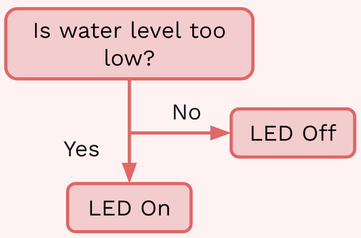
The water tower holds a water container which sits on the top, with a tube attached to the bottom and to the micro servo which lifts and lowers the tube when the soil moisture is low. There is also an LED which lights up red when the water sensor in the water container is low, indicating that the water container needs to be refilled. The wires are designed to feed through the hole in the top layer of acrylic and go through the holes in the back of the water tower, easily connecting to the arduino and perfboard which are screwed to the water tower. While in theory the wires were supposed to remain hidden inside of the water tower, having them on the outside aided in debugging purposes and were easier for prototyping.
WATER CAPACITANCE CODING LOGIC
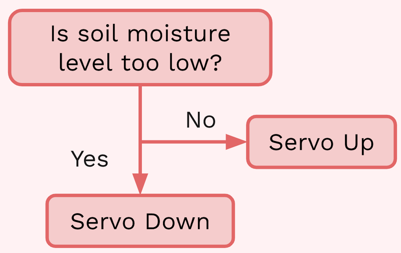
SOIL MOISTURE SENSOR CODING LOGIC
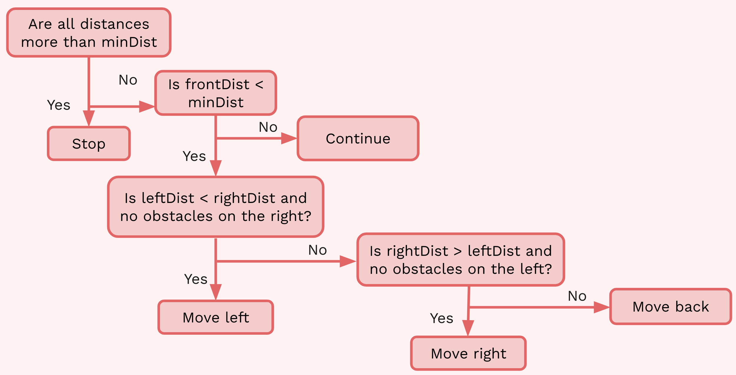
FRONT ULTRASONIC SENSOR CODING LOGIC
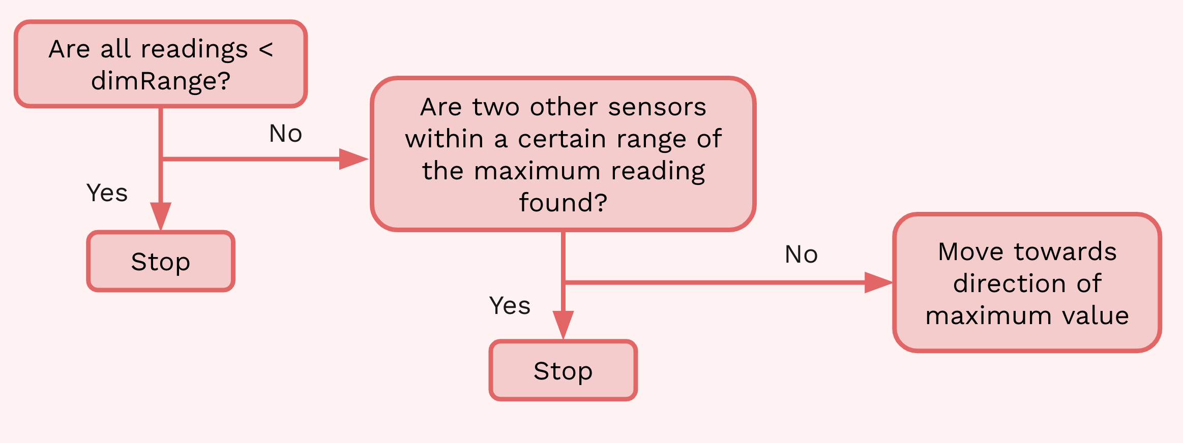
PHOTORESISTORS CODING LOGIC
THE PROBLEM
Plant care often has a lower priority in day-to-day life. Busy schedules, changes in priorities and a move back to in-person events have left plant owners without enough time to properly care for plants, necessitating the development of an autonomous robot that provides hand and hassle-free plant care.
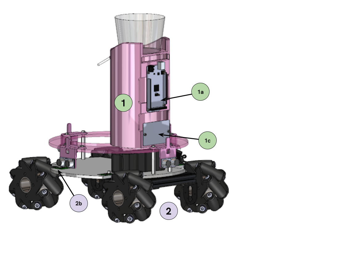
OVERALL DESIGN
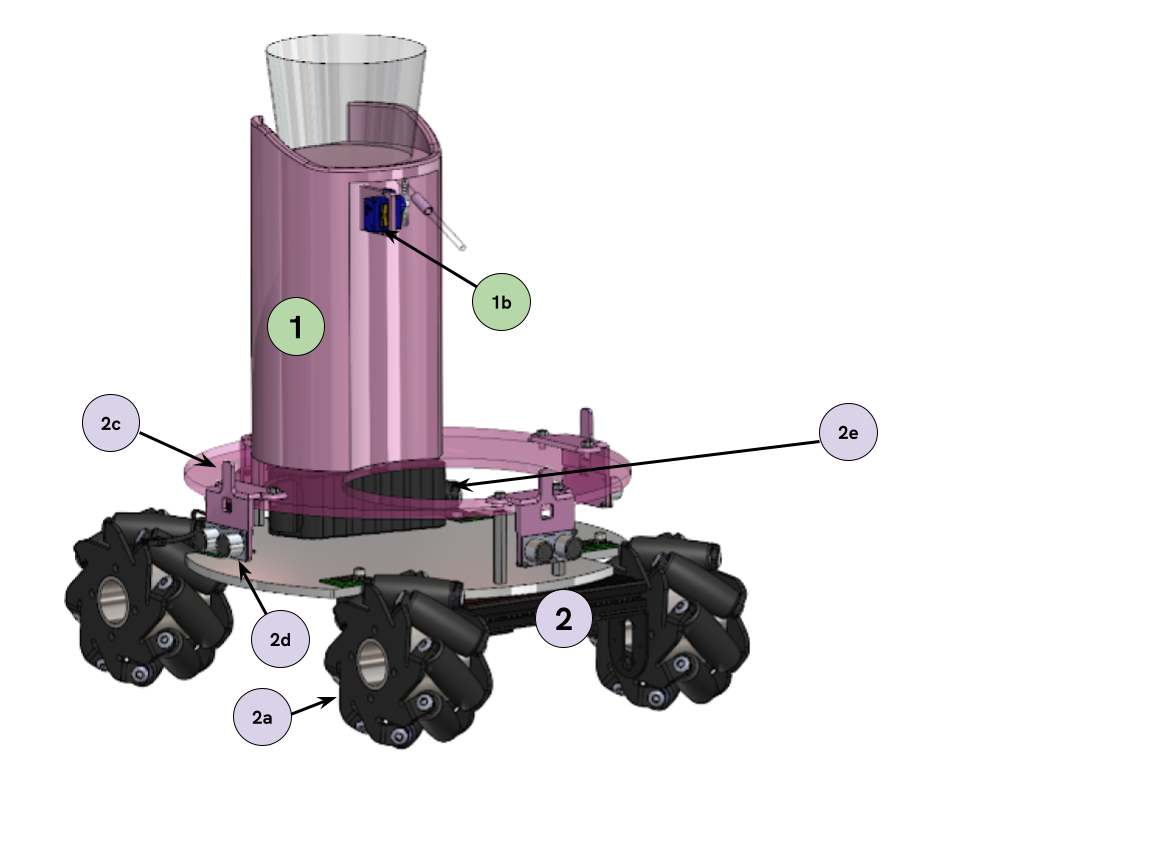
LEGEND
Water Tower
a. Arduino Mega
b. Micro servo
c. Perfboard
Chassis
a. Mecanum wheels
b. Motor controllers
c. Sensor mounts
d. Ultrasonic sensors (and Photoresistors, not shown in CAD)
e. Battery storage
CUSTOMER NEEDS
Customers seek an autonomous plant care robot that automatically waters a plant when soil moisture level is too low, is able to move the plant into an area of higher light intensity, and avoid obstacles.
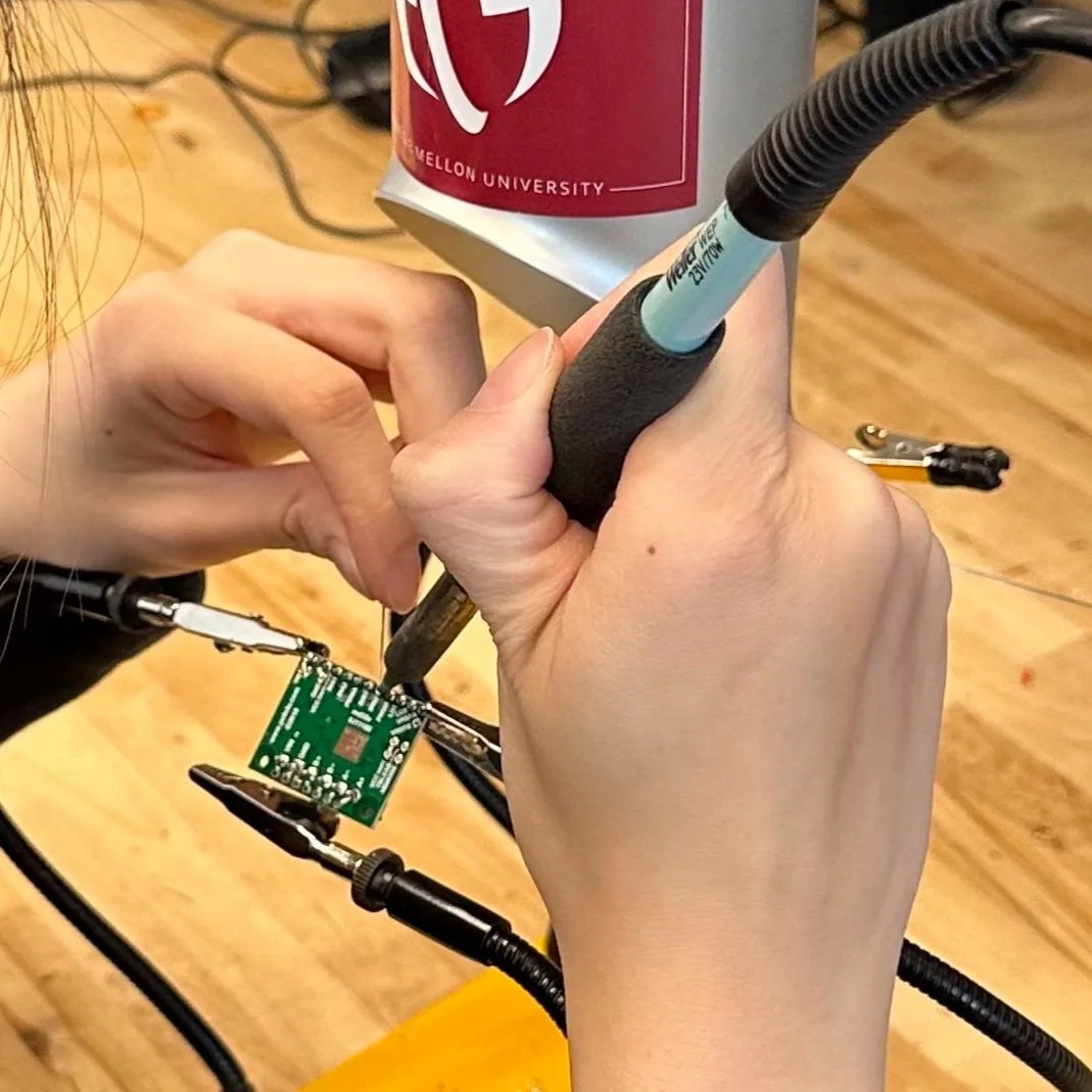
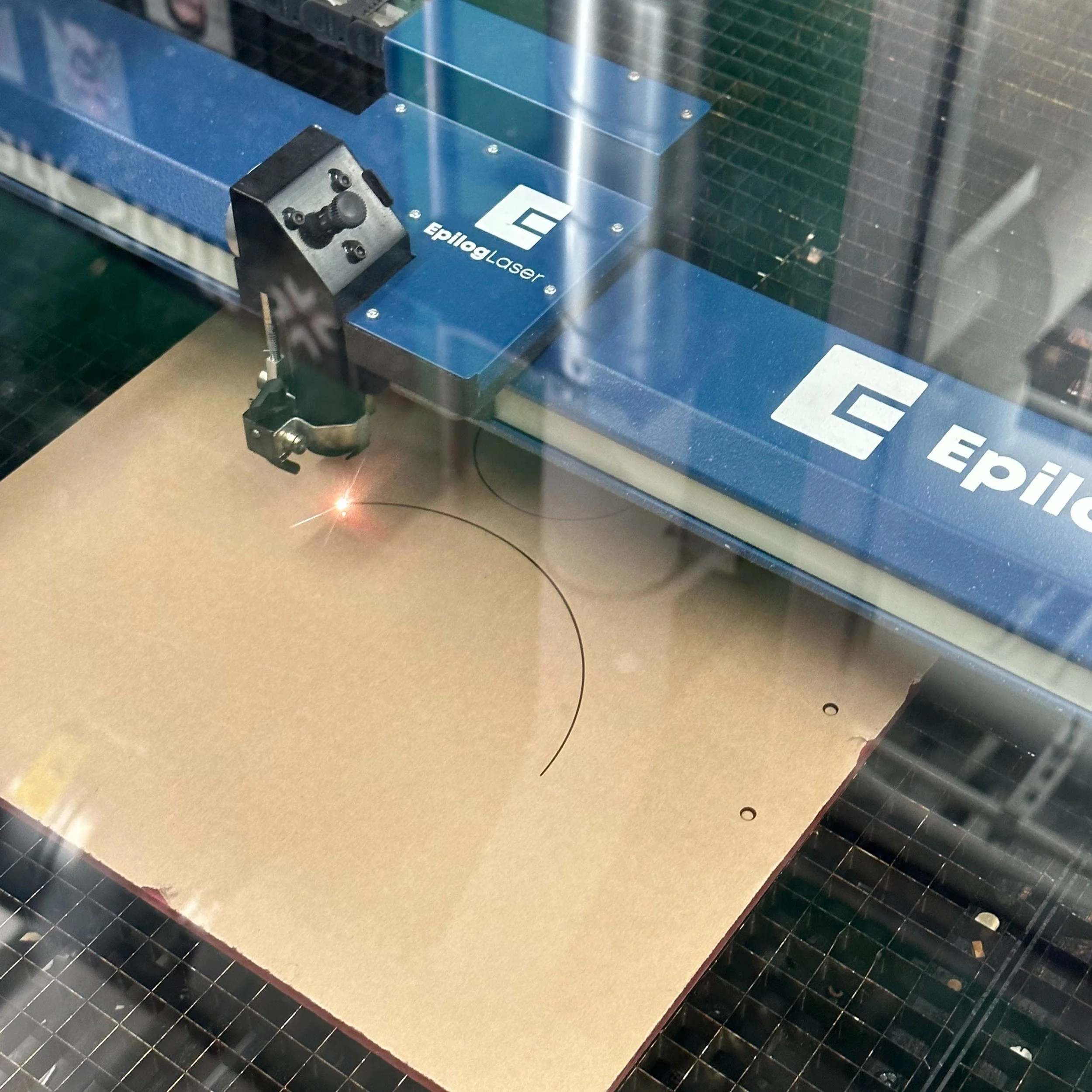
FABRICATION + Testing
All mechanical design components were fabricated using a Bambu 3D printer and by laser cutting, as these manufacturing processes were the fastest and most efficient use of our time and budget. Components such as the ultrasonic motor mounts and the water tower were 3D printed using pink matte PLA to easily produce the complex geometries needed and to match with the robot’s design and aesthetics. The chassis base was laser cut from acrylic in order to quickly make a precise and solid foundation for the robot.
FUNCTIONING PROTOTYPE Demo
PROJECT TAKEAWAYS
Our robot was able to meet all six of the initially set technical requirements! Some future improvements that could’ve been made given more time would be to finetune the drive parameters for more accurate relocation, incorporating encoder feedback or an inertial measurement unit (IMU) for the robot to recognize its current position, adding a mechanical four-bar linkage for more vertical movement of the watering tower’s tube, and to include knobs for precise user-customization.
This project taught me a lot about time management when integrating electrical components into the mechanical design (it will always take longer than we think!). A future redesign of the water tower could allow for separation of the body to reroute wires within the tower, for improved wire-management and a neater look. Overall, the robot was still successful in meeting its technical requirements and staying within the given budget, and future prototypes could be more robust in terms of testing and user customization, as well as redesigned for better aesthetics and functionality.
TECHNICAL REQUIREMENTS
The product will…
sense the intensity of light in a given position.
travel to an area with an optimal intensity of light.
be capable of traveling in a cluttered space without colliding into obstacles.
prompt the user when container water level is low.
actuate an arm that waters the plant.
be able to carry a plant that is 15 lbs.