CONEBOT
COURSE :
24-671 - Electromechanical Systems Design
TIMELINE :
September - December 2023
BUDGET:
$750
TEAM MATES:
Nate Klein, Iris Park, Hao Ding, Jaren Hubal
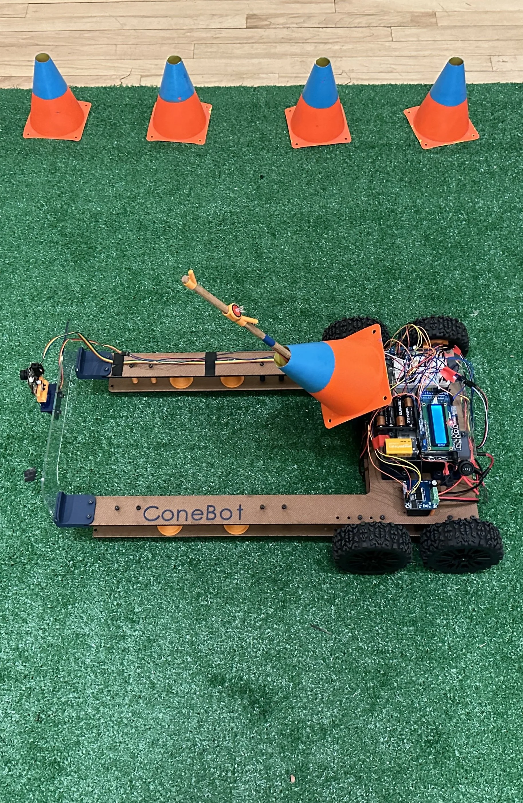
For coaches and athletes, retrieving cones between drills and after practice can be a time consuming and sometimes even painful process. ConeBot aims to address this issue with an autonomous cone retrieval and stacking system designed to assist coaches in the cone retrieval process. ConeBot saves coaches time and eliminates the physical burden of picking cones up off of the ground. It features a fully automated retrieval process, only requiring user input at the start of a cone retrieval run. ConeBot can detect cones, detect the orientations of cones, orient itself to pick up the cone, pick up the cone, store the cone, and move to the next cone fully autonomously.
Conebot won the Best Prototype Award at the Fall 2023 Design Expo.
IDEATION
For this project, Iris and I worked together on the cone retrieval and stacking mechanism, and I had an additional role as the CAD designer, and overseeing electrical integration into the mechanical design. The following sections will mainly focus on the design of the cone retrieval and stacking mechanisms for these reasons.
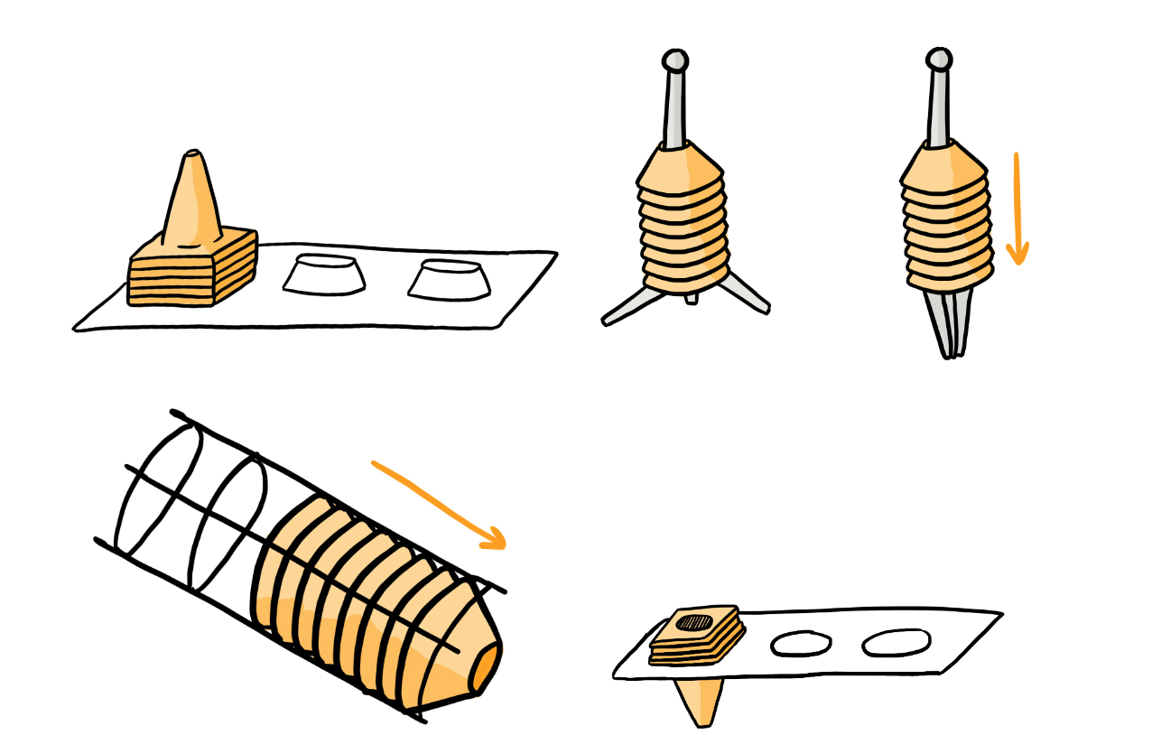
We began with some concept generation sketches. We began concept generation with separate brainstorming for the cone orientation/retrieval and the cone storage. After further discussion with the rest of the group, we all opted that the best cone retrieval and stacking mechanism given our timeline and budget would be for the chassis to have a tip plate, which is a static mechanism that knocks over an upright cone, where the hook arm, a servo-actuated cantilever arm, can then hook and latch onto the cone and lift it up into a stack.
INITIAL DESIGN + PRELIMINARY TESTING
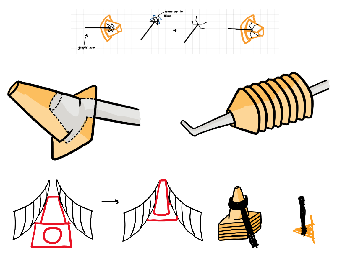
Cone orientation/retrieval concepts
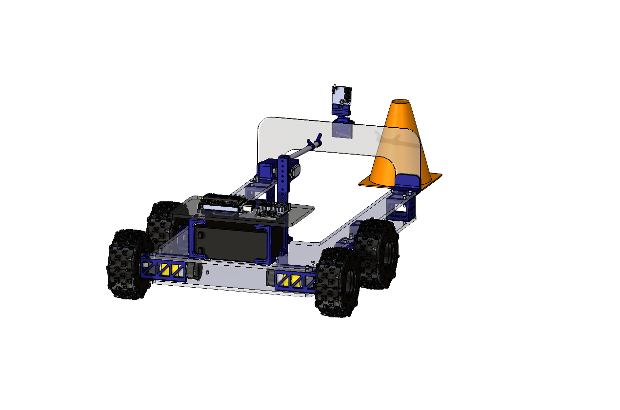
Conebot consists of a U-shaped chassis, which houses the cone retrieval and storage mechanism, the cone detection electronics, and the control center, and is responsible for maneuvering across concrete or grassy terrain.
CHASSIS DESIGN
The chassis consists of two lasercut MDF sheets, sandwiching the DC motors and motor mounts, and supported by 3D printed standoffs along the sides. The chassis is U-shaped for improved mass distribution as the robot is in motion and the cones are being collected and stored on the hook arm. The wheels are placed near the rear of the robot for more drive control, such as for turning. A rigid acrylic tip plate bridges the two chassis beams extending from the front of the robot, with the purpose of tipping over any upright cones in order for them to be retrieved later.
CONE RETRIEVAL + STORAGE
Once tipped over, cones are able to be collected with a servo-powered hook arm, which inserts into each cone and stacks them neatly. Conebot is able to tell whether or not a cone was successfully retrieved using an attached force sensor. Through hand calculations and creating torque-speed graphs, a servo was selected and an optimal hook arm length was decided upon. The servo is mounted to a 3D printed stabilizing tower, which is connected to both MDF layers of the chassis and the battery case, and keeps the hook arm secure at a height tall enough to avoid dragging the cones on the ground as the robot moved.
CONE DETECTION
The Pixycam, which is mounted to top of the tip plate, sweeps and scans using an attached microservo motor, and uses computer vision to detect color patterns on the cones. When certain color patterns were detected, Conebot is able to tell the orientation of the cone and can orient itself correctly towards the cone in preparation for a successful cone retrieval.
CONTROL CENTER
The control center consists of a LiPo battery which is enclosed by a battery case, which was designed for easy removal of the battery for when it would need to be charged. On top of the battery case, the motor driver, Arduino, and LCD screen are attached. The LCD screen is mounted to the Arduino, and functions as a user interface, where users can enter the terrain, number of cones, and more, to make Conebot function more efficiently.
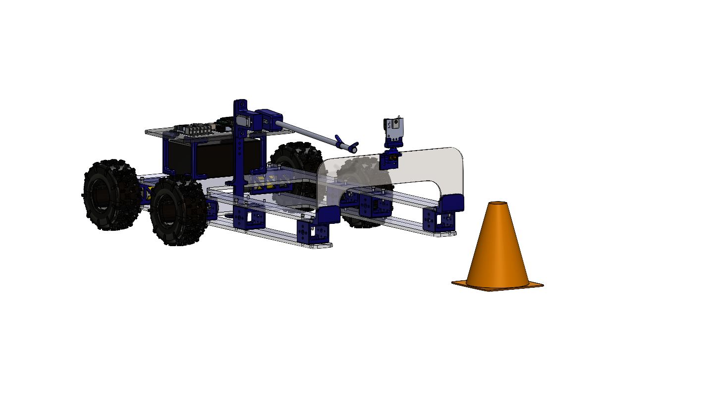
Conebot picking up successive cones.
THE PROBLEM
The ConeBot is an automated robot which detects and retrieves small athletic cones. With no current product available on the market for retrieving small athletic cones, there’s an opportunity to save coaches and athletes time spent on cleaning up after practices and drills, as well as preventing unnecessary back injuries and strain due to the repetitive motion of picking up small short cone after small short cone.
OVERALL DESIGN
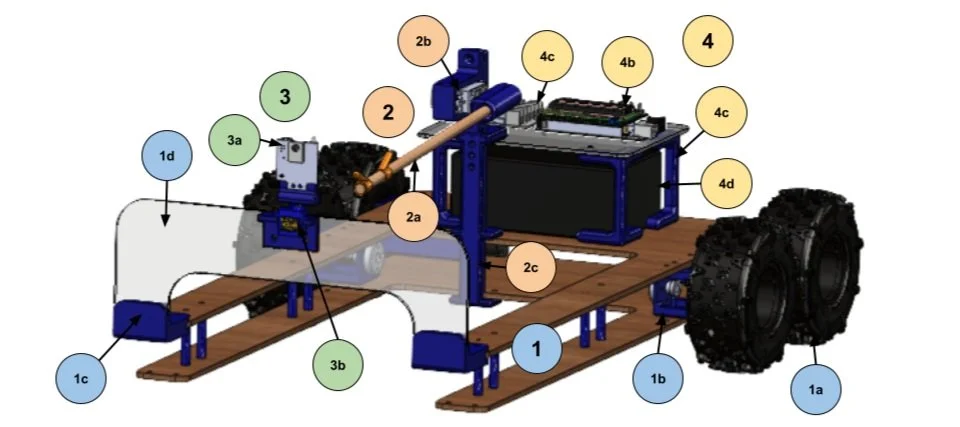
LEGEND
U-Shaped Chassis
a. Rubber wheels
b. DC motors + motor mounts
c. Tip plate mounts
d. Tip plate
Cone Retrieval + Storage
a. Hook arm + storage
b. Servo + servo mount
c. Retrieval stabilizing tower
Cone Detection
a. Pixycam
b. Microservo + tip plate mount
Control Center
a. Motor driver
b. Arduino mega + LCD screen
c. Battery case
d. LiPo battery
Cone storage concepts
For the critical design review, I modelled the assembly on SolidWorks.
Our initial prototype was made of an acrylic chassis, and had to be heavily reinforced due to the distribution of mass.
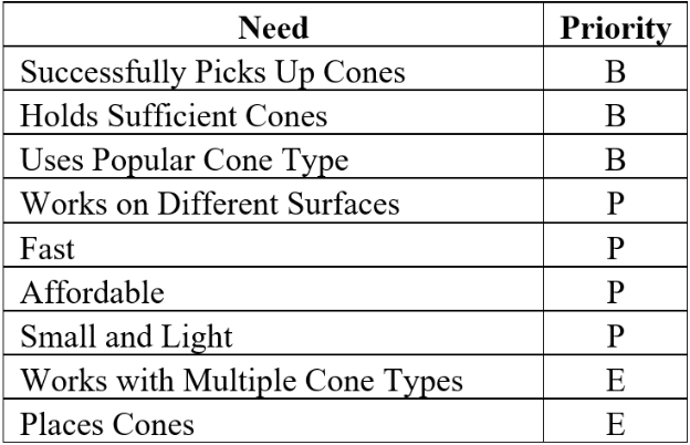
CUSTOMER NEEDS
To understand the specific needs and pain points of using athletic cones in different environments and applications, we created an online survey. We received 33 responses to our survey, with respondents including athletic coaches from Carnegie Mellon University (CMU), college students, youth athletic coaches, and physical education (PE) teachers. Through their responses, we identified many customer needs for our product.
To prioritize our customer needs, we created a chart using the Kano method, shown in the table below. Each need was given a priority of B, basic need, P, performance need, or E, exciting need. These prioritizations helped in determining the weights we gave our metrics in a scoring matrix used later.
PROTOTYPE Demo
Disclaimer: Before the design expo, our Pixycam broke and we were unfortunately unable to get a video of Conebot working with all subsystems successfully integrated, since the system relies heavily on computer vision. After the design expo, we attempted to use a new Pixycam and then accidentally shocked it and it immediately died. At this point we were reaching the limits of our budget (a pixy2 is $70!) and for these sad reasons we were unable to show Conebot at it’s fullest potential.
Conebot locating an upright cone and redirecting itself to face the cone
PROJECT TAKEAWAYS
This project was my first large project which was heavily focused on electromechanical design and integrating electronic and mechanical designs. Some important lessons learned include:
Make sure to leave extra room in the BOM for when something breaks especially when dealing with an initially tight budget and cheap and unreliable electronic components.
Triple check that the wiring schematics match up with the actual physical wiring to avoid frying anything (RIP two pixy2s and one expensive motor driver) … and on that note,
Ensure that the testing is done in a way that doesn’t jeopardize the prototype. We accidentally broke a pixycam and a tip plate from risky testing and it was expensive to fix.
I learned that I really enjoy integrating electronics into the mechanical design, and thinking about how users will interact with the robot as a whole. I also enjoyed applying theory learned in past courses to quickly write up some hand calculations or to conduct FEA, to get more reliable results.
TECHNICAL REQUIREMENTS
The product will…
be able to drive on turf, grass, hardwood, and concrete.
drive at 10 miles per hour and spend no more than 20 seconds picking up each cone.
accommodate standard, traffic-style cones.
store 10 cones.
take less than 30 seconds to retrieve the collected cone stack from the robot.
run continuously for 15 minutes on a single charge.
weigh no more than 30 pounds and fit in a car seat.

OVERVIEW OF CONE RETRIEVAL + STORAGE ENGINEERING ANALYSIS
SERVO MOTOR CALCULATIONS
Problem and Goal
The problem assessed is that the servo motor used for the hook arm needed to be strong enough to support the weight of the entire 10 cones while still being long enough to scoop up the cones and hold them in a stack. The goal was to calculate the torque needed for the servo motor attached to the hook arm and then to source a motor that meets these requirements.
Analysis Model
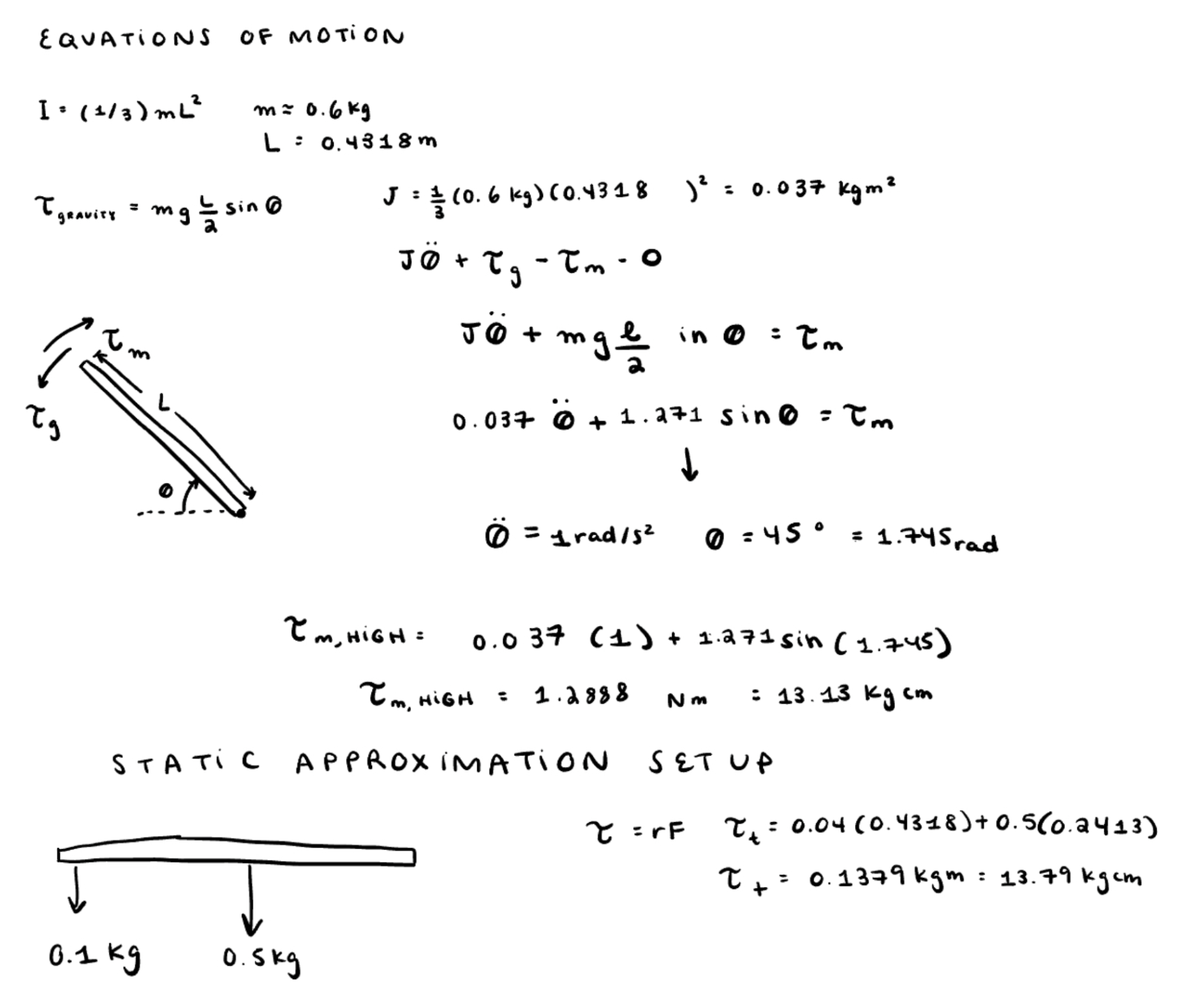
Based on estimated hook arm length values, and measured cone weight values, the torque required for the servo arm to lift the hook arm with a full set of 10 cones was estimated using the following equations of motion, as well as double-checked using the following static setup approximation.
Conclusion and Decision
The Gobilda servo motor selected matched the criteria found for the motor, which was a torque of 13.79 kgcm, and will act predictably and efficiently according to the torque-speed graphs.

Torque Requirement Calculations
Torque-speed graphs for 4.8 V (red), 6.0 V (blue), and 7.0 V (green)
TIP PLATE FEA
Problem and Goal
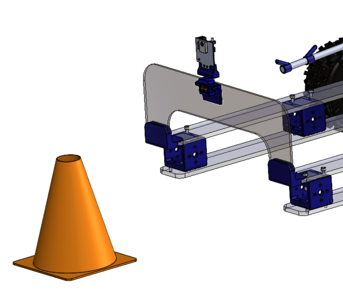
The acrylic plate at the front of the robot functions as a key component which allows the robot to tip over upright cones when driven forward. In order to successfully store 10 cones, the total length of the retrieval arm needs to be at least 8 inches long, thereby elongating the minimum length of the whole chassis. The first prototype consisted of a long acrylic plate which was bent to 90 degrees attached at the front of a shorter chassis. This initial assembly and tip plate experienced a significant amount of downward deflection due to the weight of the PixyCam and servo mounted on to the elongated acrylic tip plate. In order to alleviate this downward deflection, the team added wooden beams to support the acrylic tip plate. However, we came to the conclusion that this solution was temporary and will not be included in the final prototype as it adds extra mass to the front of the chassis.
Analysis Model
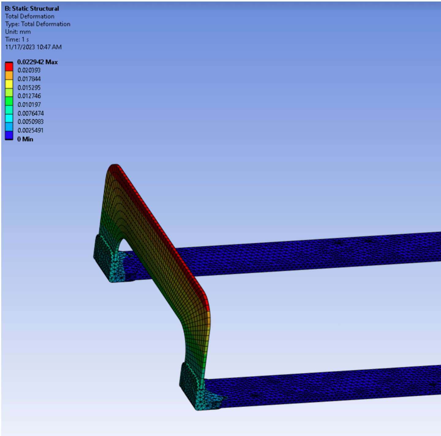
An FEA model was created in ANSYS Static Structural in order to analyze the deflection of the subsystem. The faces in which the tip plate was attached to the chassis with fasteners were constrained as fixed supports. The weight of the PixyCam and servo was modeled as a remote force at its center of mass applied to the fastener holes at which the tip plate and chassis are connected.
Conclusion and Decision
The improved design for the final iteration of the robot consists of a flat acrylic sheet mounted on an elongated chassis. The chassis plates are supported with standoffs. This updated design minimizes the maximum downward deflection from 2 mm to 0.03 mm.
Torque Requirement Calculations
Final design FEA results for downward deflection of the tip plate
Final tip plate design on CAD